Showing posts with label tutorial. Show all posts

Saturday, April 11, 2009

Step by step: interfacing a Sharp GP2D02 IR ranger

Sharp IR rangers are widely used out there. There are many different references, depending on the beam pattern, the minimal and maximal distance you want to be able to get, etc... The way you got results also make a difference: either analog (you'll get a voltage proportional to the distance), or digital (you'll directly get a digital value). This nice article will explain these details (and now I know GP2D02 seems to be discontinued...)


Overview of GP2D02 IR ranger

GP2D02 IR ranger is able to measure distances between approx. 10cm and 1m. Results are available as digital values you can access through a dedicated protocol. One pin, Vin, will be used to act on the ranger. Another pin, Vout, will be read to determine the distance. Basically, getting a distance involves the following:

  1. First you wake up the ranger and tell it to perform a distance measure
  2. Then, for each bit, you read Vout in order to reconstitute the whole byte, that is, the distance
  3. finally, you switch off the ranger

The following timing chart taken from the datasheet will explain this better.


Note: the distances obtained from the ranger aren't linear, you'll need some computation to make them so.

Sharp GP2D02 IR ranger looks like this:


  • Red wire is for +5V
  • Black wire ground
  • Green wire is for Vin pin, used to control the sensor
  • Yellow wire is for Vout pin, from which 8-bits results read
(make a mental note of this...)


Interfacing the Sharp GP2D02 IR ranger

Interfacing such a sensor is quite straight forward. The only critical point is Vin ranger pin can't handle high logic level of the PIC's output, this level mustn't exceed 3.3 volts. A zener diode can be used to limit this level.

Note: be careful while connecting this diode. Don't forget it, and don't put it in the wrong side. You may damage your sensor. And I'm not responsible for ! You've been warned... That's said, I already forgot it, put it in the wrong side, and thought I'd killed my GP2D02, but this one always got back to life. Anyway, be cautious !

Here's the whole schematic. The goal here is to collect data from the sensor, and light up a LED, more or less according to the read distance. That's why we'll use a LED driven by PWM.


Here's the ranger with the diode soldered on the green wire (which is Vin pin, using your previously created mental note...):


I've also added thermoplastic rubber tubes, to cleanly join all the wires:


Finally, in order to easily plug/unplug the sensor, I've soldered nice polarized connectors:


Writing the program

jallib >=0.3 contains a library, ir_ranger_gp2d02.jal, used to handle this kind of rangers. The setup is quite straight forward: just declare your Vin and Vout pins, and pass them to the gp2d02_read_pins(). This function returns the distance as a raw value. Directly passing pins allows you to have multiple rangers of this type (many robots have many of them arranged in the front and back sides, to detect and avoid obstacles).

Using PWM libs, we can easily make our LED more or less bright. In the mean time, we'll also transmit the results through a serial link.

var volatile bit gp2d02_vin is pin_a4
var volatile bit gp2d02_vout is pin_a6
var bit gp2d02_vin_direction is pin_a4_direction
var bit gp2d02_vout_direction is pin_a6_direction
include ir_ranger_gp2d02
-- set pin direction (careful: "vin" is the GP2D02 pin's name,
-- it's an input for GP2D02, but an output for PIC !)
gp2d02_vin_direction = output
gp2d02_vout_direction = input

var byte measure
forever loop
-- read distance from ranger num. 0
measure = gp2d02_read_pins(gp2d02_vin,gp2d02_vout)
-- results via serial
serial_hw_write(measure)
-- now blink more or less
pwm1_set_dutycycle(measure)
end loop

Note: I could directly pass pin_A4 and pin_A6, but to avoid confusion, I prefer using aliases.

A sample, 16f88_ir_ranger_gp2d02.jal, is available in jallib SVN repository, and also in jallib released packages, starting from version 0.3. You can access downloads here.


Building the whole on a breadboard

Putting all this stuff on a breadboard should be easy. Just follow the schematics :)


I usually power two tracks on the side, used for the PIC and for the ranger:


Using the same previously created mental note, I connected the yellow Vout pin using a yellow wire, and the green Vin pin using a green wire...


Testing (and the video)


Time to test this nice circuit ! Power the whole, and check no smoke is coming from the PIC or (and) the ranger. Now get an object, like you hand, more or less closed to the ranger and observe the LED, or the serial output... Sweet !


Sébastien Lelong

Saturday, February 14, 2009

Step by Step: having fun with PWM and a piezo buzzer (or a speaker) (part 2)

The last time, we had fun by controlling the brightness of a LED, using PWM. This time, we're going to have even more fun with a piezo buzzer, or a small speaker.

If you remember, with PWM, you can either vary the duty cycle or the frequency. Controlling the brightness of a LED, ie. produce a variable voltage on the average, can be done by having a constant frequency (high enough) and vary the duty cycle. This time, this will be the opposite: we'll have a constant duty cycle, and vary the frequency.


What is a piezo buzzer ?

It's a "component" with a material having piezoelectric ability. Piezoelectricity is the ability for a material to produce voltage when it get distorted. The reverse is also true: when you produce a voltage, the material gets distorted. When you stop producing a voltage, it gets back to its original shape. If you're fast enough with this on/off voltage setting, then the piezo will start to oscillate, and will produce sound. How sweet...


Constant duty cycle ? Why ?

So we now know why we need to vary the frequency. This will make the piezo oscillates more and less, and produces sounds at different levels. If you produce a 440Hz frequency, you'll get a nice A3.

But why having a constant duty cycle ? What is the role of the duty cycle in this case ? Remember: when making a piezo oscillate, it's not the amount of volts which is important, it's how you turn the voltage on/off:
  • when setting the duty cycle to 10%: during a period, piezo will get distorted 10% on the time, and remain inactive 90% on the time. The oscillation proportion is low.
  • when setting the duty cycle to 50%: the piezo is half distorted, half inactive. The oscillation proportion is high, because the piezo oscillates at the its maximal amplitude, it's half and equally distorted and inactive.
  • when setting the duty cycle to 90%: the piezo will get distorted during 90% of a period, then nothing. The oscillation proportion is low again, because the proportion between distortion and inactivity is not equal.
(I guess this is about energy or something like that. One guru could explain the maths here...)

So, to summary, what is the purpose of the duty cycle in our case ? The volume ! You can vary the volume of the sound by modifying the duty cycle. 0% will produce no sounds, 50% will be the max volume. Between 50% and 100% is the same as between 0% and 50%. So, when I say when need a constant duty cycle, it's not that true, it's just that we'll set it at 50%, so the chances we hear something are high :)


Let's produce sounds !

The schematics will use is exactly the same as on the previous post with the LED, except the LED is replaced with a piezo buzzer, like this:


By the way, how to observe the "duty cycle effect" on the volume ? Just program your PIC with the previous experiment one, which control the brightness of a LED, and power on the circuit. I wanted to show a video with sounds, but the frequency is too high, my camera can't record it...

Anyway, that's a little bit boring, we do want sounds...


Writing the software


The software part has a lot of similarities with the previous experiment. The initialization is the same, I let you have a look. Only the forever loop has changed:

var dword counter = 0
forever loop

for 100_000 using counter loop
pwm_set_frequency(counter)
-- Setting @50% gives max volume
-- must be re-computed each time the frequency
-- changes, because it depends on PR2 value
pwm1_set_percent_dutycycle(50)
end loop

end loop

Quite straightforward:
  • we "explore" frequencies between 0 and 100 000 Hz, using a counter
  • we use pwm_set_frequency(counter) to set the frequency, in Hertz. It takes a dword as parameter (ie. you can explore a lot of frequencies...)
  • finally, as we want a 50% duty cycle, and since its value is different for each frequency setting, we need to re-compute it on each loop.
Note: jallib's PWM libraries are coming from a "heavy refactoring" of Guru Stef Mientki's PWM library. While integrating it to jallib, we've modified the library so frequencies can be set and changed during program execution. This wasn't the case before, because the frequency was set as a constant.


So, how does this look like ? Hope you'll like the sweet melody :)


"Where can I download the files ?"

As usual, you'll need the last jallib pack (at least 0.2 version). You'll also find the exact code we used here.


Sébastien Lelong

Saturday, February 7, 2009

Step by Step: having fun with PWM and a LED (part 1)

Part 1 : controlling the brightness of a LED


In this "Step-by-Step" tutorial, we're going to (try to) have some fun with PWM. PWM stands for Pulse Width Modulation, and is quite weird when you first face this (this was at least my first feeling).


So, how does PWM look like ?...

PWM is about switching one pin (or more) high and low, at different frequencies and duty cycles. This is a on/off process. You can either vary:
  • the frequency,
  • or the duty cycle, that is the proportion where the pin will be high


Both have a 50% duty cycle (50% on, 50% off),
but the upper one's frequency is twice the bottom


Three different duty cycle (10%, 50% and 90%),
all at the same frequency


But what is PWM for ? What can we do with it ? Many things, like:
  • producing variable voltage (to control DC motor speed, for instance)
  • playing sounds: duty cycle is constant, frequency is variable
  • playing PCM wave file (PCM is Pulse Code Modulation)
  • ...


One PWM channel + one LED = fun

For now, and for this first part, we're going to see how to control the brightness of a LED. If simply connected to a pin, it will light at its max brightness, because the pin is "just" high (5V).

Now, if we connect this LED on a PWM pin, maybe we'll be able to control the brightness: as previously said, PWM can be used to produce variable voltages. If we provide half the value (2.5V), maybe the LED will be half its brightness (though I guess the relation between voltage and brightness is not linear...). Half the value of 5V. How to do this ? Simply configure the duty cycle to be 50% high, 50% low.

But we also said PWM is just about switching a pin on/off. That is, either the pin will be 0V, or 5V. So how will we be able to produce 2.5V ? Technically speaking, we won't be able to produce a real 2.5V, but if PWM frequency is high enough, then, on the average, and from the LED's context, it's as though the pin outputs 2.5V.


Building the whole

Enough theory, let's get our hands dirty. Connecting a LED to a PWM pin on a 16f88 is quite easy. This PIC has quite a nice feature about PWM, it's possible to select which pin, between RB0 and RB3, will carry the PWM signals. Since I use tinybootloader to upload my programs, and since tiny's fuses are configured to select the RB0 pin, I'll keep using this one (if you wonder why tinybootloader interferes here, read this post).


On a breadboard, this looks like this:


The connector brings +5V on the two bottom lines
(+5V on line A, ground on line B).


LED is connected to RB0


Writing the software

For this example, I took one of the 16f88's sample included in jallib distribution (16f88_pwm_led.jal), and just adapt it so it runs at 8MHz, using internal clock. It also select RB0 as the PWM pin.

So, step by step... First, as we said, we must select which pin will carry the PWM signals...

pragma target CCP1MUX RB0 -- ccp1 pin on B0

and configure it as output

var volatile bit pin_ccp1_direction is pin_b0_direction
pin_ccp1_direction = output
-- (simply "pin_b0_direction = output" would do the trick too)

Then we include the PWM library.

include pwm_hardware

Few words here... This library is able to handle up to 5 PWM channels (PIC using CCP1, CCP2, CCP3, CCP4 and CCP5 registers). Using conditional compilation, it automatically selects the appropriate underlying PWM libraries, for the selected target PIC.

Since 16f88 has only one PWM channel, it just includes "pwm_ccp1" library. If we'd used a 16f877, which has two PWM channels, it would include "pwm_ccp1" and "pwm_ccp2" libraries. What is important is it's transparent to users (you).

OK, let's continue. We now need to configure the resolution. What's the resolution ? Given a frequency, the number of values you can have for the duty cycle can vary (you could have, say, 100 different values at one frequency, and 255 at another frequency). Have a look at the datasheet for more.

What we want here is to have the max number of values we can for the duty cycle, so we can select the exact brightness we want. We also want to have the max frequency we can have (ie. no pre-scaler).

pwm_max_resolution(1)

If you read the jalapi documentation for this, you'll see that the frequency will be 7.81kHz (we run at 8MHz).

PWM channels can be turned on/off independently, now we want to activate our channel:

pwm1_on()

Before we dive into the forever loop, I forgot to mention PWM can be used in low or high resolution. On low resolution, duty cycles values range from 0 to 255 (8 bits). On high resolution, values range from 0 to 1024 (10 bits). In this example, we'll use low resolution PWM. For high resolution, you can have a look at the other sample, 16f88_pwm_led_highres.jal. As you'll see, there are very few differences.

Now let's dive into the loop...


forever loop
var byte i
i = 0
-- loop up and down, to produce different duty cycle
while i < 250 loop
pwm1_set_dutycycle(i)
_usec_delay(10000)
i = i + 1
end loop
while i > 0 loop
pwm1_set_dutycycle(i)
_usec_delay(10000)
i = i - 1
end loop
-- turning off, the LED lights at max.
_usec_delay(500000)
pwm1_off()
_usec_delay(500000)
pwm1_on()

end loop


Quite easy right ? There are two main waves: one will light up the LED progressively (0 to 250), another will turn it off progressively (250 to 0). On each value, we set the duty cycle with pwm1_set_dutycycle(i) and wait a little so we, humans, can see the result.

About the result, how does this look like ?


"I wanna try, where are the files ?"

To run this sample, you'll need the last jallib pack (at least 0.2 version). You'll also find the exact code we used here.


Sébastien Lelong

Sunday, January 25, 2009

Step by Step: interfacing a HD44780-compatible LCD display

In this "Step by Step" tutorial, we're going to (hopefully) have some fun with a LCD display. Particularly one compatible with HD44780 specifications, which seem to be most widely used.


Setting up the hardware

As usual, there are plenty resources on the web. I found this one quite nice, covering lots of thing. Basically, LCDs can be accessed with two distinct interfaces: 4-bit or 8-bit interfaces. 4-bit interface requires less pins (4 pins), but is somewhat slow, 8-bit interface requires more pins (8 pins) but is faster. jallib comes with the two flavors, it's up to you deciding which is most important, but usually, pins are more precious than speed, particularly when using a 16F88 which only has 16 I/O pins (at best). Since 4-bit interface seems to be most used, and we'll use this one here...

So, I've never used LCD, to be honest. Most guys consider it as an absolute minimum thing to have, since it can help a lot when debugging, by printing messages. I tend to use serial for this... Anyway, I've been given a LCD, so I can't resist anymore :)

The LCD I have seems to be quite a nice beast ! It has 4 lines, is 20 characters long.


Looking closer, "JHD 204A" seems to be the reference. Near the connector, only a "1" and a "16". No pin's name.


Googling the whole points to a forum, and at least a link to the datasheet. A section describes the "Pin Assignement". Now I'm sure about how to connect this LCD.


For this tutorial, we're going to keep it simple:
  • as previously said, we'll use 4-bit interface. This means we'll use DB4, DB5, DB6 and DB7 pins (respectively pin 11, 12, 13 and 14).
  • we won't read from LCD, so R/W pin must be grounded (pin 5)
  • we won't use contrast as well, V5 pin (or Vee) must be grounded (pin 3)
Including pins for power, we'll use 10 pins out of the 16 available, 6 being connected to the PIC (RS, EN and 4 data lines).

For convenience, I soldered a male connector on the LCD. This will help when building the whole on a breadboard.


So we now have everything to build the circuit. Here's the schematic. It also includes a LED, it will help us checking everything is ok while powering up the board.


Using a breadboard, it looks like this:


Writing the software

For this tutorial, we'll use one of the available samples from jallib repository. I took one for 16f88, and adapt it to my board (specifically, I wanted to use PORTA when connecting the LCD, and let PORTB's pins as is).

As usual, writing a program with jallib starts with configuring and declaring some parameters. So we first have to declare which pins will be connected:

-- LCD IO definition
var bit lcd_rs is pin_a6 -- LCD command/data select.
var bit lcd_rs_direction is pin_a6_direction
var bit lcd_en is pin_a7 -- LCD data trigger
var bit lcd_en_direction is pin_a7_direction

var byte lcd_dataport is porta_low -- LCD data port
var byte lcd_dataport_direction is porta_low_direction

-- set direction
lcd_rs_direction = output
lcd_en_direction = output
lcd_dataport_direction = output

This is, pin by pin, the translation of the schematics. Maybe except porta_low. This represents pin A0 to A3, that is pins for our 4 lines interface. porta_high represents pin A4 to A7, and porta reprensents the whole port, A0 to A7. These are just "shorcuts".

We also have to declare the LCD geometry:

const byte LCD_ROWS = 4 -- 4 lines
const byte LCD_CHARS = 20 -- 20 chars per line

Once declared, we can then include the library and initialize it:

include lcd_hd44780_4   -- LCD library with 4 data lines
lcd_init() -- initialize LCD

For this example, we'll also use the print.jal library, which provides nice helpers when printing variables.

include print

Now the main part... How to write things on the LCD.

  • You can either use a procedure call: lcd_writechar("a")
  • or you can use the pseudo-variable : lcd = "a"
  • lcd_setcursor(x,y) will set the cursor position. x is the line, y is the row, starting from 0
  • finally, lcd_clearscreen() will, well... clear the screen !
Full API documentation is available on jalapi.

So, for this example, we'll write some chars on each line, and print an increasing (and incredible) counter:

const byte str1[] = "Hello world!" -- define strings
const byte str2[] = "third line"
const byte str3[] = "fourth line"

print_string(lcd, str1) -- show hello world!
lcd_setcursor(2,0) -- to 3rd line
print_string(lcd, str2)
lcd_setcursor(3,0) -- to 4th line
print_string(lcd, str3)

var byte counter = 0

forever loop -- loop forever

counter = counter + 1 -- update counter
lcd_setcursor(1,0) -- second line
print_byte_hex(lcd, counter) -- output in hex format
delay_100ms(3) -- wait a little

if counter == 255 then -- counter wrap
lcd_setcursor(1,1) -- 2nd line, 2nd char
lcd = " " -- clear 2nd char
lcd = " " -- clear 3rd char
end if

end loop


The full and ready-to-compile code is available on jallib group's file section:

You'll need last jallib-pack, available on jallib's download section.


How does this look when running ?

Here's the video !


Sébastien Lelong

Tuesday, January 20, 2009

Step by Step: building an i2c slave with jallib (part 3)

Part 3 : implementing an i2c slave ISR


In previous parts of this tutorial, we've seen a little of theory, we've also seen how to check if the i2c bus is operational, now the time has come to finally build our i2c slave. But what will slave will do ? For this example, slave is going to do something amazing: it'll echo received chars. Oh, I'm thinking about something more exciting: it will "almost" echo chars:
  • if you send "a", it sends "b"
  • if you send "b", it sends "c",
  • if you send "z", it sends "{"
  • ...
(why "{" ? According to ASCII, "z" is the character for position 122. 123 is... "{")


Building the i2c master

Let's start with the easy part. What will master do ? Just collect characters from a serial link, and convert them to i2c commands. So you'll need a PIC to which you can send data via serial. I mean you'll need a board with serial com. capabilities. I mean we won't do this on a breadboard... There are plenty out there on the Internet, pick your choice. If you're interested, you can find one on my SirBot site: dedicated to 16f88, serial com. available, and i2c ready (pull-ups resistors).

It looks like this:


Two connectors are used for earch port, PORTA and PORTB, to plug daughter boards, or a breadboard in our case.

We'll use a 16f88 as a i2c master. 16f88 only own a SSP module, not MSSP, this means it can't handle i2c in hardware (no built-in i2c master). Not a problem, we'll use i2c software library.

The i2c initialization part is quite straight forward. SCL and SDA pins are declared, we'll use a standard speed, 400KHz,


-- I2C io definition
var volatile bit i2c_scl is pin_b4
var volatile bit i2c_scl_direction is pin_b4_direction
var volatile bit i2c_sda is pin_b1
var volatile bit i2c_sda_direction is pin_b1_direction
-- i2c setup
const word _i2c_bus_speed = 4 ; 400kHz
const bit _i2c_level = true ; i2c levels (not SMB)
include i2c_software
i2c_initialize()

We'll also use the level 1 i2c library. The principle is easy: you declare two buffers, one for receiving and one for sending bytes, and then you call procedure specifying how many bytes you want to send, and how many are expected to be returned. Joep has written a nice post about this, if you want to read more about this. We'll send one byte at a time, and receive one byte at a time, so buffers should be one byte long.
const single_byte_tx_buffer = 1 -- only needed when length is 1
var byte i2c_tx_buffer[1]
var byte i2c_rx_buffer[1]
include i2c_level1

What's next ? Well, master also has to read chars from a serial line. Again, easy:

const usart_hw_serial = true
const serial_hw_baudrate = 57_600
include serial_hardware
serial_hw_init()
-- Tell the world we're ready !
serial_hw_write("!")

So when the master is up, it should at least send the "!" char.


Then we need to specify the slave's address. This is a 8-bits long address, the 8th bits being the bit specifying if operation is a read or write one (see part 1 for more). We then need to collect those chars coming from the PC and sends them to the slave.

The following should do the trick (believe me, it does :))


var byte icaddress = 0x5C -- slave address

forever loop
if serial_hw_read(pc_char)
then
serial_hw_write(pc_char) -- echo
-- transmit to slave
-- we want to send 1 byte, and receive 1 from the slave
i2c_tx_buffer[0] = pc_char
var bit _trash = i2c_send_receive(icaddress, 1, 1)
-- receive buffer should contain our result
ic_char = i2c_rx_buffer[0]
serial_hw_write(ic_char)
end if
end loop


The whole program is available on jallib SVN repository here (subject to change, since not released yet).


Building the i2c slave

So this is the main part ! As exposed on first post, we're going to implement a finite state machine. jallib comes with a library where all the logic is already coded, in a ISR. You just have to define what to do for each state encountered during the program execution. To do this, we'll have to define several callbacks, that is procedures that will be called on appropriate state.

Before this, we need to setup and initialize our slave. i2c address should exactly be the same as the one defined in the master section. This time, we won't use interrrupts on Start/Stop signals; we'll just let the SSP module triggers an interrupts when the i2c address is recognized (no interrupts means address issue, or hardware problems, or...). Finally, since slave is expected to receive a char, and send char + 1, we need a global variable to store the results. This gives:

include i2c_hw_slave

const byte SLAVE_ADDRESS = 0x5C
i2c_hw_slave_init(SLAVE_ADDRESS)

-- will store what to send back to master
-- so if we get "a", we need to store "a" + 1
var byte data

Before this, let's try to understand how master will talk to the slave (red) and what the slave should do (green), according to each state (with code following):
  • state 1: master initiates a write operation (but does not send data yet). Since no data is sent, slave should just do... nothing (slave just knows someone wants to send data).
procedure i2c_hw_slave_on_state_1(byte in _trash) is
pragma inline
-- _trash is read from master, but it's a dummy data
-- usually (always ?) ignored
end procedure

  • state 2: master actually sends data, that is one character. Slave should get this char, and process it (char + 1) for further sending.
procedure i2c_hw_slave_on_state_2(byte in rcv) is
pragma inline
-- ultimate data processing... :)
data = rcv + 1
end procedure

  • state 3: master initiates a read operation, it wants to get the echo back. Slave should send its processed char.
procedure i2c_hw_slave_on_state_3() is
pragma inline
i2c_hw_slave_write_i2c(data)
end procedure

  • state 4: master still wants to read some information. This should never occur, since one char is sent and read at a time. Slave should thus produce an error.
procedure i2c_hw_slave_on_state_4() is
pragma inline
-- This shouldn't occur in our i2c echo example
i2c_hw_slave_on_error()
end procedure

  • state 5: master hangs up the connection. Slave should reset its state.
procedure i2c_hw_slave_on_state_5() is
pragma inline
data = 0
end procedure

Finally, we need to define a callback in case of error. You could do anything, like resetting the PIC, and sending log/debug data, etc... In our example, we'll blink forever:

procedure i2c_hw_slave_on_error() is
pragma inline
-- Just tell user user something's got wrong
forever loop
led = on
_usec_delay(200000)
led = off
_usec_delay(200000)
end loop
end procedure

Once callbacks are defined, we can include the famous ISR library.
include i2c_hw_slave_isr

So the sequence is:
  1. include i2c_hw_slave, and setup your slave
  2. define your callbacks,
  3. include the ISR


The full code is available from jallib's SVN repository (caution, not released yet, could be modified):


You'll also need jallib-pack from here. Copy the two libraries to the "lib" directory, compile the two samples and program two 16f88.

(Edit on 01/30: libraries and samples are now include in jallib's version > 0.1, no extra download needed !)

Connecting and testing the whole thing...

As previously said, the board I use is ready to be used with a serial link. It's also i2c ready, I've put the two pull-ups resistors. If your board doesn't have those resistors, you'll have to add them on the breadboard, or it won't work (read part 2 to know and see why...).

I use a connector adapted with a PCB to connect my main board with my breadboard. Connector's wires provide power supply, 5V-regulated, so no other powered wires it required.

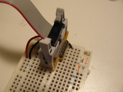
Connector, with power wires


Everything is ready...


Crime scene: main board, breadboard
and battery pack


Once connected, power the whole and use a terminal to test it. When pressing "a", you'll get a "a" as an echo from the master, then "b" as result from the slave.


What now ?

We've seen how to implement a simple i2c hardware slave. The ISR library provides all the logic about the finite state machine. You just have to define callbacks, according to your need.

i2c is a widely used protocol. Most of the time, you access i2c devices, acting as a master. We've seen how to be on the other side, on the slave side. Being on the slave side means you can build modular boards, accessible with a standard protocol. For instance, I've build a DC motor controller daughter board using this. It's a module, a unit on its own, just plug, and send/receive data, with just two wires.

And I also plan to build a LCD controller board, but that's for another "Step by Step" post :)


Reading:


Sébastien Lelong

Saturday, January 17, 2009

Step by Step: building an i2c slave with jallib (part 2)

Part 2 : checking the hardware and the i2c bus...


Last time, we saw a basic overview of how to implement an i2c slave, using a finite state machine implementation. Today, we're going to get our hands a little dirty, and starts connecting our master/slave together.

First of all, i2c is quite hard to debug, especially if you don't own an oscilloscope (like me). So you have to be accurate and rigorous. That's why, in this second part of this tutorial, we're going to setup the hardware, and just make sure the i2c bus is properly operational.

Connecting two PIC together through i2c is quite easy from a hardware point of view. Just connect SDA and SCL together, and don't forget pull-ups resistors. There are many differents values for these resistors, depending on how long the bus is, or the speed you want to reach. Most people use 2.2K resistors, so let's do the same ! The following schematics is here to help:


In this circuit, both PIC have a LED connected, which will help us understand what's going on. On a breadboard, this looks like that:


The master is on the right side, the slave on the left. I've put the two pull-ups resistors near the master:


Green and orange wires connect the two PICs together:


The goal of this test is simple: check if the i2c bus is properly built and operational. How ? PIC 16F88 and its SSP peripheral is able to be configured so it triggers an interrupts when a Start or Stop signal is detected. Read this page (part of an nice article on i2c, from last post's recommandations).

How are we gonna test this ? The idea of this test is simple:

  1. On power, master will blink a LED a little, just to inform you it's alive
  2. On the same time, slave is doing the same
  3. Once master has done blinking, it sends a i2c frame through the bus
  4. If the bus is properly built and configured, slave will infinitely blink its LED, at high speed

Note master will send its i2c frame to a specific address, which don't necessarily need to be the same as the slave one (and I recommand to use different addresses, just to make sure you understand what's going on).

What about the sources ? Download last jallib pack, then go get some other libraries and samples (those files aren't release yet, API may change):


(Edit on 01/30: those libraries and samples are now included in jallib's version > 0.1. No extra download needed)


The main part of the slave code is the way the initialization is done. A constant is declared, telling the library to enable Start/Stop interrupts [edit on 01/30, API has changed, previously init was taking a true/false parameter]:


const SLAVE_ADDRESS = 0x23 -- whatever, it's not important, and can be
-- different from the address the master wants
-- to talk to
-- with Start/Stop interrupts
const bit i2c_enable_start_stop_interrupts = true
-- this init automatically sets global/peripherals interrupts
i2c_hw_slave_init(SLAVE_ADDRESS)


And, of course, the Interrupt Service Routine (ISR):

procedure i2c_isr() is
pragma interrupt
if ! PIR1_SSPIF then
return
end if
-- reset flag
PIR1_SSPIF = false
-- tmp store SSPSTAT
var byte tmpstat
tmpstat = SSPSTAT
-- check start signals
if (tmpstat == 0b_1000) then
-- If we get there, this means this is an SSP/I2C interrupts
-- and this means i2c bus is properly operational !!!
while true loop
led = on
_usec_delay(100000)
led = off
_usec_delay(100000)
end loop
end if
end procedure


The important thing is to:
  • check if interrupt is currently a SSP interrupts (I2C)
  • reset the interrupt flag,
  • analyze SSPSTAT to see if Start bit is detected
  • if so, blinks 'til the end of time (or your battery)


Now, go compile both samples, and program two PICs with them. With a correct i2c bus setting, you should see the following:


On this next video, I've removed the pull-ups resistors, and it doesn't work anymore (slave doesn't high speed blink its LED).


Next time (and last time on this topic), we'll see how to implement the state machine using jallib, defining callback for each states.

Reading:


Sébastien Lelong

Wednesday, January 14, 2009

Step by Step: building an i2c slave with jallib (part 1)

Part 1 : a few words before getting our hands dirty...

i2c is a nice protocol: it is quite fast, reliable, and most importantly, it's addressable. This means that on a single 2-wire bus, you'll be able to plug up to 128 devices using 7bits addresses, and even 1024 using 10bits address. Far enough for most usage... I won't cover i2c in depth, as there are plenty resources on the Web (and I personally like this page).

i2c is found in many chips and many modules. Most of the time, you create a master, like when accessing an EEPROM. This time, in this tutorial, we're going to build a slave, which will thus respond to master's requests.

The slave side is somewhat more difficult because, as it does not initiate the talk, it has to listen to "events", and be as responsive as possible. You've guessed, we'll use interrupts. I'll only cover i2c hardware slave, that is using SSP peripheral (note: some PICs have MSSP, this means they can also be used as i2c hardware Master). Implementing an i2c software slave may be very difficult (and I even wonder if it's reasonable...).

There are different way implementing an i2c slave, but one seems to be quite common: defining a finite state machine. This implementation is well described in Microchip AppNote AN734 . It is highly recommended that you read this appnote, and the i2c sections of your favorite PIC datasheet as well (I swear it's quite easy to read, and well explained).

Basically, during an i2c communication, there can be 5 distinct states:
  1. Master writes, and last byte was an address : to sum up, master wants to talk to a specific slave, identified by the address, it wants to send data (write)
  2. Master writes, and last byte was data : this time, master sends data to the slave
  3. Master read, and last byte was an address : almost the same as 1., but this time, master wants to read something from the salve
  4. Master read, and last byte was data : just the continuation of state 3., master has started to read data, and still wants to read more data
  5. Master sends a NACK : basically, master doesn't want to talk to the slave anymore, it hangs up...

Note: in i2c protocol, one slave has actually two distinct addresses. One is for read operations, and it ends with bit 1. Another is for write operations, and it ends with bit 0.

Ex: consider the following address (8-bits long, last bit is for operation type)

0x5C => 0b_0101_1100 => write operation

The same address for read operation will be:

0x93 => 0b_0101_1101 = read operation


[EDIT: jallib currently supports up to 128 devices on a i2c bus, using 7-bits long addresses (without the 8th R/W bits). There's currently no support for 10-bits addresses, which would give 1024 devices on the same bus. If you need it, please let us know, we'll modify libraries as needed !]

OK, enough for today. Next time, we'll see how two PICs must be connected for i2c communication, and we'll check the i2c bus is fully working, before diving into the implementation.


Reading:


Sébastien Lelong