Setting up the hardware
As usual, there are plenty resources on the web. I found this one quite nice, covering lots of thing. Basically, LCDs can be accessed with two distinct interfaces: 4-bit or 8-bit interfaces. 4-bit interface requires less pins (4 pins), but is somewhat slow, 8-bit interface requires more pins (8 pins) but is faster. jallib comes with the two flavors, it's up to you deciding which is most important, but usually, pins are more precious than speed, particularly when using a 16F88 which only has 16 I/O pins (at best). Since 4-bit interface seems to be most used, and we'll use this one here...
So, I've never used LCD, to be honest. Most guys consider it as an absolute minimum thing to have, since it can help a lot when debugging, by printing messages. I tend to use serial for this... Anyway, I've been given a LCD, so I can't resist anymore :)
The LCD I have seems to be quite a nice beast ! It has 4 lines, is 20 characters long.
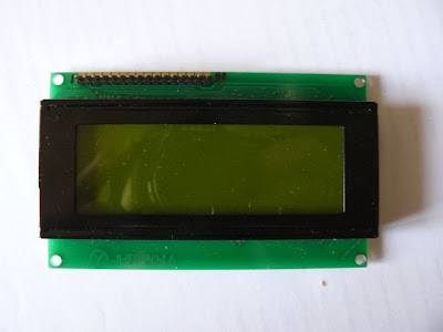
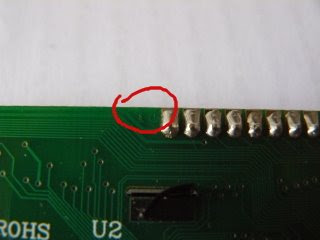
Looking closer, "JHD 204A" seems to be the reference. Near the connector, only a "1" and a "16". No pin's name.
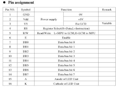
Googling the whole points to a forum, and at least a link to the datasheet. A section describes the "Pin Assignement". Now I'm sure about how to connect this LCD.
For this tutorial, we're going to keep it simple:
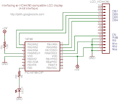
- as previously said, we'll use 4-bit interface. This means we'll use DB4, DB5, DB6 and DB7 pins (respectively pin 11, 12, 13 and 14).
- we won't read from LCD, so R/W pin must be grounded (pin 5)
- we won't use contrast as well, V5 pin (or Vee) must be grounded (pin 3)
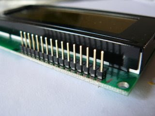
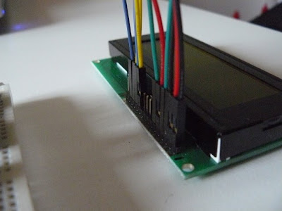
For convenience, I soldered a male connector on the LCD. This will help when building the whole on a breadboard.
So we now have everything to build the circuit. Here's the schematic. It also includes a LED, it will help us checking everything is ok while powering up the board.
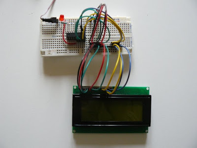
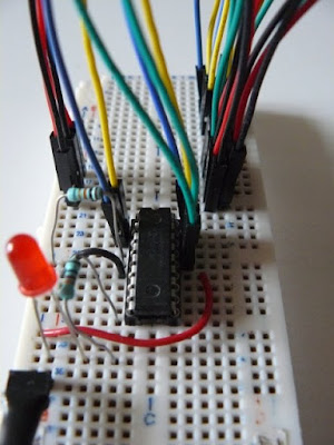
Using a breadboard, it looks like this:
Writing the software
For this tutorial, we'll use one of the available samples from jallib repository. I took one for 16f88, and adapt it to my board (specifically, I wanted to use PORTA when connecting the LCD, and let PORTB's pins as is).
As usual, writing a program with jallib starts with configuring and declaring some parameters. So we first have to declare which pins will be connected:
This is, pin by pin, the translation of the schematics. Maybe except porta_low. This represents pin A0 to A3, that is pins for our 4 lines interface. porta_high represents pin A4 to A7, and porta reprensents the whole port, A0 to A7. These are just "shorcuts".
We also have to declare the LCD geometry:
Once declared, we can then include the library and initialize it:
For this example, we'll also use the print.jal library, which provides nice helpers when printing variables.
Now the main part... How to write things on the LCD.
So, for this example, we'll write some chars on each line, and print an increasing (and incredible) counter:
The full and ready-to-compile code is available on jallib group's file section:
You'll need last jallib-pack, available on jallib's download section.
How does this look when running ?
Here's the video !
Sébastien Lelong
As usual, writing a program with jallib starts with configuring and declaring some parameters. So we first have to declare which pins will be connected:
 -- LCD IO definition
var bit lcd_rs           is pin_a6              -- LCD command/data select.
var bit lcd_rs_direction is pin_a6_direction
var bit lcd_en           is pin_a7              -- LCD data trigger
var bit lcd_en_direction is pin_a7_direction

var byte lcd_dataport is porta_low              -- LCD data  port
var byte lcd_dataport_direction is porta_low_direction

-- set direction
lcd_rs_direction = output
lcd_en_direction = output
lcd_dataport_direction = output
This is, pin by pin, the translation of the schematics. Maybe except porta_low. This represents pin A0 to A3, that is pins for our 4 lines interface. porta_high represents pin A4 to A7, and porta reprensents the whole port, A0 to A7. These are just "shorcuts".
We also have to declare the LCD geometry:
const byte LCD_ROWS     = 4      -- 4 lines
const byte LCD_CHARS    = 20     -- 20 chars per line
Once declared, we can then include the library and initialize it:
include lcd_hd44780_4   -- LCD library with 4 data lines
lcd_init()              -- initialize LCD
For this example, we'll also use the print.jal library, which provides nice helpers when printing variables.
include printNow the main part... How to write things on the LCD.
- You can either use a procedure call: lcd_writechar("a")
- or you can use the pseudo-variable : lcd = "a"
- lcd_setcursor(x,y) will set the cursor position. x is the line, y is the row, starting from 0
- finally, lcd_clearscreen() will, well... clear the screen !
So, for this example, we'll write some chars on each line, and print an increasing (and incredible) counter:
const byte str1[] = "Hello world!"      -- define strings
const byte str2[] = "third line"
const byte str3[] = "fourth line"

print_string(lcd, str1)                 -- show hello world!
lcd_setcursor(2,0)                      -- to 3rd line
print_string(lcd, str2)
lcd_setcursor(3,0)                      -- to 4th line
print_string(lcd, str3)

var byte counter = 0

forever loop                            -- loop forever

   counter = counter + 1                -- update counter
   lcd_setcursor(1,0)                   -- second line
   print_byte_hex(lcd, counter)         -- output in hex format
   delay_100ms(3)                       -- wait a little

   if counter == 255 then               -- counter wrap
      lcd_setcursor(1,1)                -- 2nd line, 2nd char
      lcd = " "                         -- clear 2nd char
      lcd = " "                         -- clear 3rd char
   end if

end loop
The full and ready-to-compile code is available on jallib group's file section:
You'll need last jallib-pack, available on jallib's download section.
How does this look when running ?
Here's the video !
Sébastien Lelong


